


In the sections below, you will find information about geostationary and polar-orbiting weather satellites, how to construct and use inexpensive direct read-out receiving stations, and links to resources with more information.
Geostationary satellites orbit the Earth over the equator at an altitude of about 36,000 km (22,000 miles). Their speed matches the rotation rate of the Earth so they appear to be stationary over the same ground location. There are two NOAA Geostationary Operational Environmental Satellites (GOES) in active operation designated GOES-East at 75.2° west longitude and GOES-West at 137.2° west longitude (currently GOES-16 and GOES-18, respectively).
Of the GOES-R Series of satellites, GOES-R, -S, and -T are currently operational and designated GOES-16, -17, and -18, respectively, after launch and reaching stable orbit. GOES-17 is currently on-orbit backup. The newly designed instruments on GOES-R Series satellites include an enhanced "solar observatory", a space environment suite, the new Geostationary Lightning Mapper (GLM), and Advanced Baseline Imager (ABI) which detects 16 discrete wavebands of data. Compared to sensors on the earlier GOES-N Series satellites, the ABI provides three times more spectral information at four times the spatial resolution and more than five times faster temporal coverage.
For the do-it-yourself hobbyist or student, there are two signal types easily receivable from GOES-R series satellites: GRB and HRIT.
The GOES-R Series satellites's scientific instruments sense the environment and distribute data to the onboard computer for processing and distribution to the X-band antenna for transmission to Earth as a digital data stream. The GOES Rebroadcast (GRB) provides the primary GOES-16 and GOES-17 relay of full resolution, calibrated, near-real-time direct broadcast Level 1b data from each instrument (ABI, space environment, and solar data) and Level 2 data from the Geostationary Lightning Mapper (GLM).
The NOAA/NESDIS High Rate Information Transmission / Emergency Managers Weather Information Network (HRIT/EMWIN) broadcast provides a GOES-R Series relay of reduced resolution imagery in the HRIT/LRIT format along with other information. LRIT (Low Resolution Information Transmission) was available from GOES-N Series (GOES-13, 14, 15). It was phased out in December 2017 (GOES East) and February 2019 (GOES west) as GOES-16 and 17, respectively, became operational and replaced their earlier counterparts.
To directly receive imagery from GOES and other geostationary and polar-orbiting satellites, a variety of manufacturers offer equipment and software packages. NOAA/NESDIS provides a list of manufacturers for your review. Some of those venders are well established, having demonstrated their equipment at the early Satellites & Education Conferences, and their systems have evolved with the times. Do-it-yourselfers, students, and teachers on a budget can build and operate their own effective yet inexpensive systems...see below.
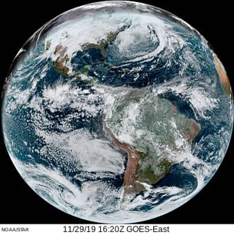
Image Credit: NOAA from the GOES Image Viewer.
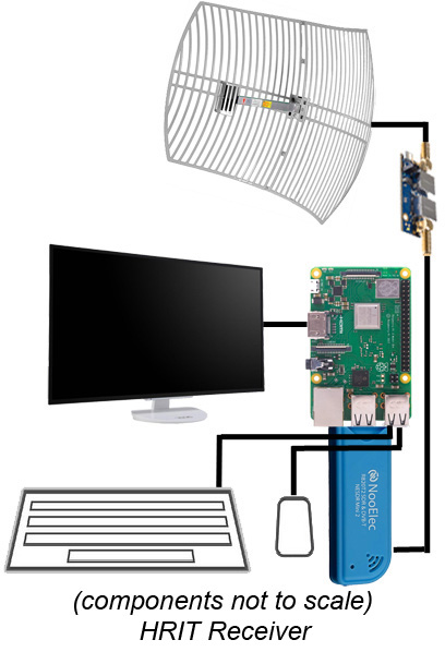
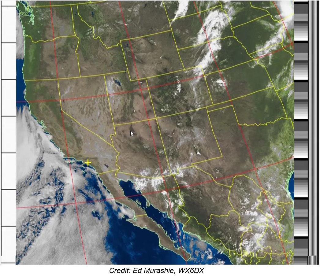
For do-it-yourselfers and those with limited budgets, building your own GOES direct read-out station for HRIT is within reach and relatively easy. As software-defined radio (SDR) has become more available and popular, the cost of materials to assemble and operate your own GOES receiving station has become quite affordable. You can see GOES weather satellite images in real time as they are transmitted directly from the satellites. NOAA/NESDIS gives a full description of the Aerospace HRIT/EMWIN Prototype receiver developed for NASA/NOAA. But you can construct an even more affordable system. SEA member Ed Murashie, President of ProEngineered Solutions in Santa Ana, California shows us how to do it...
The GOES-R Series HRIT system transmits on L-band at 1694.1 MHz with BPSK (binary phase shift keying) modulation. The antenna has a linear polarization with vertical effect. Basically, this home-built system works this way: the antenna (designed for 1694.1 MHz) receives the transmitted signal which is amplified by the low noise amplifier (LNA). The amplified signal is fed into a software-defined radio (SDR) tuner (a USB dongle) plugged into a Linux-based computer (Raspberry Pi 3). The Raspberry Pi contains all programming (free downloads) on a Mini SD card. It outputs to a HDMI monitor and is controlled with keyboard and mouse connected by USB. Cost? Around $200 assuming you already have monitor, keyboard and mouse. This does not include RG6 coax antenna cable. The cost of the cable will vary depending on its length. The cable and all connectors and adapters are described in the links below. You may also want to consider adding enclosures for the Raspberry Pi and LNA, and a mast for the antenna.

GOES HRIT Overview (5:13) *
GOES Rebroadcast (GRB) can also be received at home or in the classroom with software defined radio, a computer, and software available online. The antenna is different and the system a little more complex than the HRIT system just described, but still within range. All sixteen ABI bands can be received, stored and imaged with this home-built station. Thanks to Ed Murashie for this video describing the components, how they fit together and operate.

GOES GRB Overview (5:12) *
* These videos are viewed in Dropbox. Feel free to close any Dropbox "Sign Up/Sign In" pop-up overlays before viewing videos.
NOAA weather satellites in near polar-orbiting are designated NOAA-x. The most recent addition to the Joint Polar Satellite System (JPSS), JPSS-1, was redesignated NOAA-20 when it became operational in 2017. JPSS is a combination of NOAA POES (Polar Orbiting Environmental Satellites) program with NASA EOS (Earth Observing System) and the Department of Defense.
Of the older POES satellites, NOAA-18 and NOAA-19 are still functional and transmitting both APT and HRPT image data. These are perhaps the easiest weather satellite signals to receive at home or in the classroom.
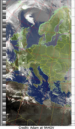
Automatic Picture Transmission (APT) is an analog facsimile signal. Two wavebands are transmitted simultaneously: visible and thermal infrared. The sample image shown here was offered by Adam, 9A4QV. The receiving station was in Europe. The white background of the timing strip on the right side of the image tells us this infrared. The gray scale consists of 256 shades of gray. Darker pixels indicate warmer temperatures and lighter pixels represent cooler temperatures. On command, the receiving software added false color to the image as well as the political boundaries. The date of the image is unknown. Viewed together with the visible image, forecasters were able to identify weather conditions and monitor climate over the long term.
The APT facsimile signal is in the very high frequency (VHF) range close to the amateur 2-meter band at 137.xx MHz. The signal from the radio receiver can be processed through the audio circuitry ("sound card") and programming of a personal computer. Receiving and imaging software often include orbital prediction routines (a program for predicting when the satellite will be overhead and "visible" to the receiving antenna).
High Rate Picture Transmission (HRPT) is a digital signal with greater spatial resolution than APT. It consists of four wavebands of data, one visible and three infrared. In addition to temperature of surface features and atmospheric components, users can differentiate between clouds, snow, and ice, and ocean/land boundaries become more distinct. With greater spatial resolution, one can zoom-in to see more detail.
The digital HRPT signal is in the microwave range near 1700 MHz. While the same orbital predict routines can be used, a different antenna, receiving software, and imaging software are needed. The receiving station for HRPT is a little more complex than APT.
The antenna is one of the most important components of a radio receiver and sometimes the last considered when building the receiver or transmitter. In simplest terms, an antenna is an electrically conductive wire connected to your radio transmitter or receiver; a wire in which a passing wave of electromagnetic radiation (radio wave) induces an electric current. Amateur radio enthusiasts and engineers have been designing and analyzing antennae of all shapes, sizes and configurations for decades. Generally, the best antenna has a length one-half or one-quarter of the wavelength of the radio waves the antenna is intended to receive. The relationship between wavelength, frequency, and the velocity of electromagnetic radiation is defined by dimensional analysis in c=λν where c is the velocity of electromagnetic radiation in vacuum or in the specific metal of the antenna (meters/second), λ is the wavelength of the signal (meters), and ν is the frequency of the signal (second-1 also called Hertz). This relationship is discussed in detail in the lesson module for middle and high school Electromagnetic Radiation & Satellites - Antenna Design from the SEA Lesson Plan Library.
Effective antennae include, among other things, a reflector in addition to the detector element. The reflector helps concentrate the passing radio waves on the detector to increase the gain of the received signal. Remember, polar orbiting APT transmit in the very high frequency (VHF) range at 137.xx MHz while polar orbiting HRPT and geostationary weather satelites transmit in the microwave range, like 1691 MHz, for example. Consequently, microwave antennae are very small and require large reflectors for effective use. Reflectors for microwave antennae are generally parabolic in shape, with the actual antenna mounted in a feed horn (essentially a resonating can) at the focal point. Parabolic "dish" reflectors for home or school use are often 6 to 12 feet in diameter or more. The larger the dish, the more gain for the antenna.
Specific information about building an antenna for each reception type is included in the video tutorials.
The do-it-yourself receiving station for polar-orbiting weather satellites is not unlike the system described above for receiving GOES HRIT imagery. Software defined radio (SDR) is still the choice for radio receiver as the antenna cable attaches directly to the SDR's USB dongle. In the video tutorials below, a desktop computer is used instead of Raspberry Pi. The video tutorial includes mention of needed supplies, equipment, software and construction tips as well as operation.
The antenna described in this video was designed by Adam, 9A4QV. You will find it remarkably easy and inexpensive to build. It provides unexpectedly clear results.

NOAA APT Overview (5:39) *

APT Antenna (13:57) *
The HRPT antenna described in this tutorial is a small dish that tracks the satellite across the sky while Adam's APT antenna is stationary. The tutorial includes mention of needed supplies, equipment, software and construction tips as well as operation.

NOAA HRPT Overview (6:09) *
* These videos are viewed in Dropbox. Feel free to close any Dropbox "Sign Up/Sign In" pop-up overlays before viewing videos.
Sound complicated? Not really! Check out these web sites for directions and illustrations. Some of these sites include how to receive APT from NOAA polar-orbiting weather satellites.
Most of these sites have lots of additional links for parts, instructions, hints & tips. Many have boards for posting comments and questions. Licensed amateur radio operators will always extend a helping hand when they are able.
You are invited to explore these areas in sequence or skip to the topic of greatest interest: